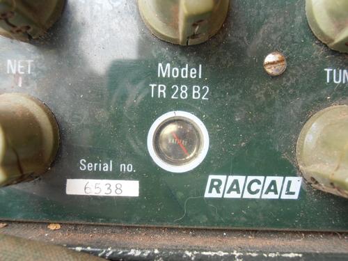
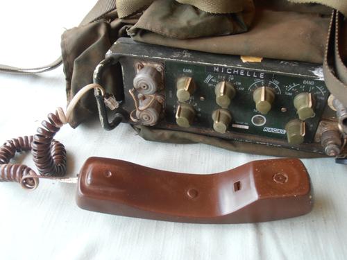
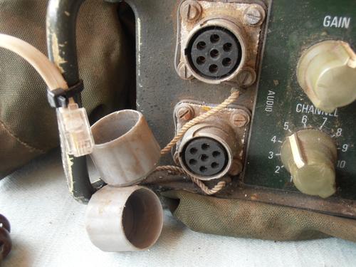
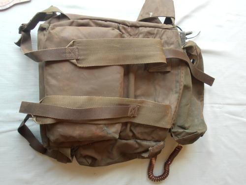
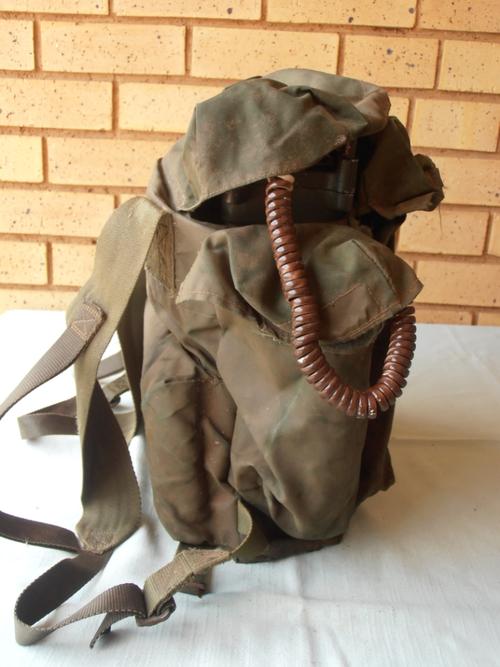
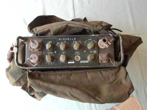
The Racal Grinaker TR28B2 manpack SSB transceiver The SSB Manpack and its pioneers in Southern Africa
FINAL DRAFT
by Brian Austin, PhD, C.Eng, FIEE, G0GSF (ex ZS6BKW)
The account by Pat Hawker in R.B.45 on the evolution of the solid-state manpack radio provided valuable background information about this important piece of military communications hardware. What it really brought home was how the manpack, or packset, had developed in the twenty years since the end of the Second World War. Then, the cumbersome and hopelessly underpowered WS 68, as used at Arnhem, fulfilled this role in the British Army but seldom with great success. It was replaced in the 1960s by the A13, A14 and A16 with higher power and improved performance in every respect. All were much more rugged in their construction though some still required considerable muscle-power to hump them around. In addition, phase modulation (PM) was adopted, at least in some of the types, instead of the amplitude modulation (AM) capability of their predecessors. Of course, CW still played a significant part in military communications at that time and all equipments provided for it though it was hardly the mode to use when on the move!
What
was also obvious from the article was the dominance exerted by the
Signals Research and Development Establishment (SRDE) on the whole
design and procurement process in England. This proved to be a
double-edged sword as electronics surged ahead in the era of the
transistor. In addition, as the article also made clear,
single-sideband or SSB had already been seen in other quarters as the
way to go. This article deals with the development of the SSB
manpack, not in England but in South Africa, and the influence it had
on military communications well beyond its own shores.
Some SSB Background
Single Sideband (SSB) modulation completely changed the face of HF communications when it first appeared as a viable alternative to amplitude modulation (AM) in the 1950s. Its history, though, is far older than that and one has to go back to 1923 to see the original patent granted to John R. Carson of the American Telephone and Telegraph Company for "A Method and Means for Signaling (sic) with High Frequency Waves". Even more intriguing is the fact that the patent was originally filed on 1 December 1915, the year after Carson had proved mathematically that sidebands existed above and below the carrier signal. The eight-year hiatus between those two dates was caused by a heated debate as to whether Carson’s calculations were just mathematical fiction! His patent shows a transmitter with balanced modulator and bandpass filter remarkably similar in concept to the circuits used today and a receiver with, what we might call today, its carrier insertion oscillator.
By
1927, fixed channel trans-Atlantic SSB was a reality. Progress,
however, was slow and it was not until 1957 that the first
commercial-grade equipment made by the Collins Radio Company of Cedar
Rapids, USA, appeared. Oscillator stability, especially when
continuous tuning was required, proved to be the major hurdle but it
was O.G.Villard (W6QYT), a professor at Stanford University, who
showed that the immediate post-war technology was up to the task. In
1947, "Mike" Villard put the University’s amateur radio
station, W6YX, on the air on SSB and this started a surge of interest
in this new mode of communications. But other radio amateurs had been
there before. According to the American Radio Relay League (ARRL)
publication "Single Sideband for the Radio Amateur" (1965)
there were perhaps as many as half a dozen amateur SSB stations on
the air as early as 1934 following some pioneering work done by one
Robert Moore, W6DEI. But the ARRL’s own views at the time were that
SSB would require a level of technical expertise beyond that of radio
amateurs and so further work was shelved. Such timidity, however, is
the very gauntlet that inspires a reaction and so it was elsewhere
too, as we will see.
SSB, Radio Amateurs and the Military
Radio amateurs in the earlier days of the hobby were, by and large, inveterate builders of their own equipment. Amongst them, too, were those who rose to every new challenge and one of those was the exciting subject of "single sideband suppressed carrier", SSSC, soon to known by the more euphonious SSB. By contrast, and despite some popular misconceptions, military communicators were seldom the trailblazers when it came to pioneering the latest techniques. So it was with SSB.
The first SSB equipment to see service with the British Army was the Clansman series introduced after interminable delays during the 1970s. By then the pioneering radio amateurs had a head start of many years. The Army’s decision to change from the AM equipment of the wartime era and the more recent adaptation Phase Modulation (PM) to SSB was taken in 1966. However, the wheels of military specification and procurement turn slowly and, as Pat Hawker pointed out it, took some major restructuring of the Signals Research and Development Establishment (SRDE) at Christchurch before things really started to happen. Intriguingly, the real inspiration behind the decision to ditch a technology no longer suited to the highly congested HF spectrum in favour of one that was may well have come from an unexpected quarter South Africa.
In the early months of the Second World War, the South African forces were not overly endowed with modern signals equipment but there was an embryonic radio industry that soon rose to the challenge. In Durban, Horace Dainty (ZS5HT later ZS5C) had established The Radio Electro-Equipment Company (soon to become the S.M.D Manufacturing Company) in 1937 selling electronic components and manufacturing radio receivers and transmitters. On the day after South Africa declared war on Germany, he sent a terse telegram to the Postmaster General: "Can make transmitters", it said. Almost immediately he was requested to make a 150W HF transmitter for use in Port Elizabeth for communication with the Royal Navy’s vessels in the Indian Ocean. It was duly delivered within a month and commissioned by Dainty himself. A number of orders soon followed for various items of equipment that rapidly caused S.M.D to turn its facilities over to full-scale wartime production. Both the South African Air Force and Army soon were using S.M.D’s 150 watt AM transmitters in their ground stations and at headquarters. That equipment saw service both in the East African campaign to drive the Italians from Abyssinia and, later, in the Middle East with the 8th Army. The largest order from the South African Army was for 400 30W HF transmitter/receivers to be installed in armoured cars. The prototype appeared in just four weeks and became the M17. As often happens, however, its reputation was marred by the Army’s insistence on using just an 8 foot (2.4m) rod antenna without any inductive loading. A considerable reduction in working range was the obvious result.
S.M.D had established its reputation in the field of military communications equipment during the war. When peace eventually returned the company was therefore in a unique position in the early 1950s when the South African Council for Scientific and Industrial Research (CSIR) was seeking an industrial partner to build six pre-production versions of the famous Wadley drift-cancelling, continuously tuneable, HF receiver. Trevor Wadley, the Durban-born designer of this remarkable receiver had originally conceived the idea when developing a novel ionosonde a radar-type device for measuring the characteristics of the ionosphere immediately after the war. He was then working in the Telecommunications Research Laboratory (TRL) of the CSIR in Johannesburg following his own wartime service in the S.A. Corps of Signals. There, in its Special Signals Service, Wadley had made significant contributions towards improving the performance of the South African-designed radars that ringed the country’s very long coastline. Those six prototype receivers that S.M.D built soon confirmed everything that Wadley had said his receiver could do and the CSIR duly patented the design and its underlying principles. It was now time to move into commercial production and the seventh receiver to be built was the prototype of a commercial model with the serial number 007. It was made at S.M.D. by David Larsen, (ZS5DN later ZS6DN), who was soon to become a pioneer himself in the design of solid-state SSB equipment and a leading figure in the South African electronics industry.
And
so began the long and very successful partnership between Horace
Dainty and David Larsen (Fig 1) who undoubtedly must be counted
amongst the pioneers of single sideband radio communications.
Enter Racal and SSB
In 1954, the struggling Racal Company in England turned Larsen’s prototype of the Wadley receiver into one of the most famous radio receivers ever manufactured - the RA17. It entered service with the Royal Navy and soon established itself as a most remarkable piece of equipment in terms of stability and ease of operation. In keeping with the technology of the time its modes were AM and CW; SSB had not yet become part of the military communications armoury. Technology advances quickly; the logistics of equipment procurement do not.
The RA17 was undoubtedly the making of Racal. But there was even more to come and much of it, too, came from South Africa. In March 1963, Racal UK became a major shareholder in RACAL S.M.D. with Racal-SMD eventually becoming Racal Electronics South Africa (RESA) after moving from Durban to Pretoria, where it was situated close to the industrial and military heart of South Africa. The relocation of S.M.D actually saw it split two ways: one part going north to Pretoria, as mentioned, while the other shuffled just a short way to its new home, still in Natal, where it became part of the large Barlows industrial group and was soon to be the main supplier of all VHF equipment to the South African Defence Force.
In
the early 1960s, by which time SSB transmitters and receivers using
valve technology were already well established in the radio amateur
literature (and in some shacks too) the British Army introduced its
Larkspur series of radios into service. Short-range tactical nets
made use of the VHF spectrum for the first time with FM being the
modulation mode. However, the Larkspur HF equipment for the
longer-range circuits was still based on AM or PM and, of course, CW.
The underlying design philosophy, which was essentially conservative,
was both determined and carefully controlled by the Signals Research
and Development Establishment (SRDE), as we have seen. So-called
private-venture designs by companies not working closely with the
SRDE were not much favoured. This meant that in 1966 a piece of
equipment that fell into that category, the Racal solid-state SSB
manpack known as the TRA 906 or "Squadcal", was never
acquired by the British Army even though more than 25 000 were sold
abroad to approximately 50 countries. For this information I am
indebted to Geoff Bennett, G3CYL, who was Racal’s Marketing Manager
for South East Asia at the time and then ultimately Managing Director
of Racal Radio Ltd.
Of particular interest is the fact that the Squadcal was actually based on a solid-state manpack designed in South Africa by David Larsen and known there initially as the RT14; see Fig.2. In 1972, Mr E.T. (later Sir Ernest) Harrison, Chairman of the Racal Group, paid tribute in a press release to both Horace Dainty and David Larsen. It was the Mr Larsen, he said, "who had been responsible for the development of equipment which had enabled Racal International to reach its dominating position, particularly in the world of military mobile communications. Racal UK was exporting more manpacks than any other company in the world and they had been developed from designs which originated through Mr Larsen in South Africa". Keith Thrower, until recently Research Director of the Racal Radio Group, provided some of the background surrounding the story of the RT14/Squadcal in his June 2003 article in "Transmission Lines", the newsletter of the Defence Electronics History Society. It will be expanded upon here.
The genesis of the RT14 can actually be traced to the late 1950s when Larsen designed S.M.D.’s first SSB exciter using transistors when these devices were little more than electronic curiosities. Naturally enough, the transmitter was put through its paces on the amateur bands where it soon came to the attention of the Americans, most notably that of Don Stoner, W6TNS. Stoner, well-known as a pioneer in the field of single sideband and solid-state circuits, had published his "New Sideband Handbook" in 1958, just a year after the appearance of the very first book to deal with the subject in any depth, the Collins Radio Company’s "Fundamentals of SSB". Larsen and Stoner subsequently collaborated closely. The American was full of ideas, particularly on crystal filters, and was also a ready source of components that were hard to come by in South Africa. His attempts, though, to persuade Dave Larsen to join him in the USA were unsuccessful after the South African had astutely weighed up all his options.
By
the early ‘60s QST, the ARRL’s monthly magazine, had already
featured many articles on the theory and practice of single sideband
and a selection of the best formed the basis of the ARRL book,
"Single Sideband for the Radio Amateur", published in 1965.
Except for two, all the circuits were based on valve (or tube)
technology. Those exceptions were a remarkable 14 MHz transistorised
transceiver, described as being the "ultra-ultra in
compactness", designed by Benjamin J.Vester, W3TLN, and the "Imp
-TR" a solid-state transmitter of Joseph S. Galeski, W4IMP,
first published in QST in December 1961. Some of the circuitry
Galeski used and the assistance he needed in getting started all came
from Dave Larsen and Joe Galeski made full acknowledgement to ZS5DN
for that.
The RT14 manpack
Not
only was the Larsen SSB exciter the model for that "Imp TR"
but, far more importantly, it also formed the basis of S.M.D.’s
first SSB transceiver, the transistor-valve hybrid known as the RT422
and its later model the RT422B (Fig.3). This transportable
combination that included a linear amplifier may well have been the
world’s first commercial, transistor-valve, "filter-type"
SSB transceiver. It started life as an amateur radio venture and was
built by David Larsen over the two week Christmas holiday period of
1959/60. Like all his homebrew designs it soon found its way into the
S.M.D design register, many of which later became commercial
products. Its possible competitors for this title might include the
Redifon GR.410, based on the so-called "third method" of
SSB generation, which was first marketed in 1962. Shortly
thereafter, the S.M.D. circuit reappeared in the RT14, the all
transistorised manpack soon to become the Squadcal in England and the
TR28 in South Africa. This crucial circuit, and the broadband
solid-state power amplifier that followed it, could probably lay
claim to having launched the SSB manpack on the world stage. Its only
apparent competitor was the American-manufactured Hughes HC-162,
described by Pat Hawker in his Radio Bygones article, which made its
appearance in England in 1963. A remarkable design for its time, the
HC-162 included a 10 000 channel frequency synthesizer compared with
the 29 crystal-controlled channels of the Squadcal or the 12, 24 or
36 channels of the TR28, shortly to appear. However, it was very much
more expensive than its British and South African competitors and
yet, other than its synthesizer, it offered nothing more by way of
performance.
Fig.4 is the circuit diagram of the SSB
exciter section of both the RT14 and the RT422B. It has been re-drawn
from David Larsen’s original diagram of 1959 but retains its
authenticity by using the symbol for the PNP bipolar transistor in
use at that time. Its similarity with that of a triode valve will be
obvious.
There are a number of noteworthy features in this circuit that merit some comment. First, is the use throughout of germanium transistors in the famous OC70 and OC170 series from Mullard; next is the remarkable simplicity of the circuit itself: two stages of audio amplification following the microphone; the simplest of diode balanced modulator driven by an un-buffered crystal oscillator; a full lattice filter using four, carefully selected, war surplus FT-243 crystals that had been carefully "doctored" by the merest pencil mark or a wipe with a piece of solder to shift their frequencies downwards ever so slightly. Then came the piece de resistance - an amplifier, tuned to the centre frequency of the crystal filter, which incorporated a logarithmic compression network of four diodes shunting a high-Q tuned circuit. Since this element of the RT14 proved so controversial when first examined in England, yet so effective when tested in the field, more will be said about it later.
Following
the microphone amplifier (in RT422B exciter) is a four-diode bridge
and four common emitter amplifiers and switches. This is the VOX and
anti-VOX circuitry providing the voice-operated switching from
receive to transmit. It will be noted, too, that the drawing
includes, in block diagram form, the channel oscillator and mixer
plus valve driver (type 5763) and the push-pull, linear, output stage
consisting of two 6146s, so typical of the transmitters then
available on the radio amateur market that featured these ubiquitous
beam power tubes. The receiver was a conventional superhet whose IF
bandwidth was determined by that same crystal filter after suitable
switching into the receive path. Fig 5 shows the original RT14 in its
sheet metal container with a centre-loaded and base-matched whip
antenna during field trials in South African in 1964. Just evident,
as well, is the shroud over the top panel-mounted loudspeaker that
also doubled as the microphone. This novel approach would not have
gone down well with soldiers attempting, by all means possible, to
operate in a clandestine fashion! The next model, the RT14B (as shown
in Fig 2), used the more conventional telephone handset. (Note:
Increasing the transmitted "talk power" by means of the "RF
clamping diodes" held the transmitters PEP output at a constant
pre-set level and avoided the necessity of ALC control in the final
power amplifier. For "commercial security" reasons the "RF
clamping diodes" were not shown in the early RT422B circuit
diagrams.)
A sceptical response
Early in 1963 Horace Dainty, Managing Director of Racal-SMD, took the RT14 to England in order to demonstrate it to his major shareholder at the Racal headquarters in Bracknell. The reaction he got was mixed. Viewed superficially the simple and inexpensive construction and the rather primitive case in which it was housed (looking like a biscuit tin, some said), may have contributed to this. However, the 5W PEP broadband, linear, power amplifier did intrigue Racal’s engineers who had not come across the particular circuit configuration before. It bore a marked similarity to the push-pull audio amplifiers then in common use in the transistor portable radio market. And so it should, since that was exactly the technology upon which it was based, but the clever use of ferrite-cored transformers and low impedance inter-stage coupling allowed it to operate at much higher frequencies. For all that, there were those who had serious misgivings about the RT14’s ability to meet the SRDE’s requirements based, as they were, on a strict interpretation of CCITT specifications, especially those related to stability and out-of-band emissions. In Bracknell particular criticism was levelled at the RF speech processing circuit with its propensity, so some believed, to generate quite unacceptable distortion products when subjected to a conventional "two-tone test". When this pessimistic view was confirmed by the SRDE itself, after the RT14 was shown to them, Horace Dainty returned to South Africa feeling somewhat perplexed.
Before
he left, though, he impressed upon Ray Brown and Ernie Harrison who,
with Calder Cunningham, were instrumental in founding and fostering
the Racal company, the absolute need to "get into the lower cost
market" if they wished to remain competitive. By then, more than
600 of the RT422B transceivers were in service in various parts of
southern Africa where they were used, often under the most demanding
conditions, in both fixed localities and in vehicles and frequently
by very inexperienced operators. Despite this, and without having
complied with any "mil-spec" in their design, their
performance and serviceability were reported to be excellent. When
David Larsen, by now Technical Director of Racal-SMD, heard how the
RT14 had come in for what he considered to be ill-informed criticism
he was incensed. "We’re interested in communications, not
specifications", he said when told that it was those CCITT
specifications, as well as the almost esoteric "Fletcher-
Munsen" audio intelligibility curves, that had floored his
brainchild. At Horace Dainty’s invitation he duly headed for
England on the next available flight to confront the sceptics.
RF speech processing and short antennas
Amongst Larsen’s many objectives on arriving at Bracknell was to convince Racal’s engineers that his method of modifying the speech waveform in the transmitter produced a marked improvement in the signal-to-noise ratio at the receiver without also causing any significant increase in distortion products, either in-band or out-of-band. There was more, too. After much experimentation Racal-SMD had developed a technique of matching to 50W the impedance of a short whip antenna on an operator’s back by using just a single rotary inductor. This, too, was an important and useful technique they might wish to use.
David Larsen’s undoubted powers of technical persuasion (as well as Horace Dainty’s commercial pep talk, one must assume) led, over the next couple of years, to a series of visits by Racal’s engineers to South Africa and to further trips by Larsen himself to England. It soon became clear that the South African company had developed an uncomplicated, yet highly effective piece of equipment that was apparently quite unique. Since RF speech processing was the key to its performance - and is now recognized almost as a sine qua non in SSB transmitters - the method he devised will be described briefly. In addition, his simple yet effective method of feeding the short whip antenna on the RT14 will also be touched upon.
Typically, unprocessed speech has a ratio of instantaneous peak to average power of about 15 dB, see Fig 6. In a peak power limited system, such as an SSB transmitter, this represents a considerable loss of potential output power so some means of compressing the dynamic range of the speech signal is required before transmission. It is now well known that clipping (or hard limiting) the peaks of an SSB waveform, and then filtering by a second bandpass filter similar to that in the SSB generator to remove the resulting harmonic and high-order products, can markedly improve the articulation index of the transmitted signal. Ways of doing this were just being developed in the early 1960s when David Larsen designed his system.
Instead of just clipping the peaks, followed by filtering, it worked on the principle of changing, dynamically, the Q of a tuned circuit that formed the load of a common emitter amplifier. Fig 7 shows two ways of achieving this. In (a) a diode is tapped across just a portion of the tuned circuit. On certain peaks of the signal the diode will conduct but instead of clipping ferociously it can be made to react logarithmically by appropriate choice of the tapping point for a given signal level and diode characteristic (i.e. Ge or Si). The effect of this controlled conduction is equivalent to loading the tuned circuit by a variable resistor which, effectively lowers its Q and hence its impedance in a variable way. Since the gain of the amplifier is proportional to its collector load it decreases on signal peaks and so compresses the SSB signal’s dynamic range. In (b) the same effect occurs but here the chain of diodes only conducts at a higher voltage so they can be connected across the complete tuned circuit an easier option in practice since it obviates the need for the inductor tap. This latter method was used in the RT14 with suitable pre-emphasis of the voice frequencies (provided by the type of microphone used) to ensure the appropriate balance between vowel sounds and sibilance.
This form of RF speech processing was well ahead of its time. The acid test of its effectiveness was to compare two transmitters of equal peak envelope power: one processed, the other not. If specifications mattered more than performance then a spectrum analyser would produce all the numbers but say nothing about the quality of communications. However, such instruments were rare in those days and so other simpler, yet ingenious methods, which said a lot about both, had to be used instead. Most often the test instruments consisted of an in-line RF power meter and a selective receiver. Whistling into the microphone (by sucking not blowing) produces a very good sinewave. This would then drive the transmitter to its maximum PEP output. Replacing the whistle by a long "aaaah" sound, of no intelligibility but considerable utility to both man and beast, simulates well a continuous waveform containing a range of speech frequencies. When used to drive an unprocessed SSB transmitter it produces an output 10 to 15 dB below the whistle, which clearly emphasises the point made above. By contrast, the same whistle and primeval "aaaah", when fed through the processed system, might differ by less than a decibel in output level.
Many would argue that an "on the air" comparison is the only meaningful arbiter of effectiveness. Such comparative listening tests, of which Racal-SMD had conducted a good few, confirmed that the increased "talk power" of the processed signal brought about a marked improvement in the received signal-to-noise ratio (SNR), while not introducing significant distortion products either within the audio passband or in its adjacent channels. In fact, it was so good in this respect that one of Racal-SMD’s customers used to run independent radio nets on the same frequency, one on LSB the other on USB! This increase in SNR was equivalent to that obtained by increasing the power output of an unprocessed 5W transmitter by as much as 10 dB to 50W. Since every watt on a man’s back mattered as more power always means larger batteries and heavier sets, this was not to be sneezed at. In addition, short, inefficient whip antennas are often obligatory for both practical and tactical reasons; therefore optimum transmitter performance is vital.
Those whip antennas are frequently no more than 8 feet or 2.4m long. Their already poor efficiency at HF must not compromised further by inadequate coupling both to the transmitter and to the ground which, after all, is very much part of the antenna circuit. The Racal-SMD approach was to use a "body capacity plate" of wire gauze ("fly screen") built into the shoulder pads, the operator’s belt and the back of the carrying harness for the RT14. These capacity plates were then inter-connected and joined by a flexible lead to the earth terminal of the radio. Their effect was to increase the capacitive coupling between the case of the radio and the operator’s body and thence to the ground. By so doing the effectiveness of the antenna system improved markedly. This occurred because the losses associated with the already compromised short monopole, and the operator’s body, were reduced. Of particular interest was the finding that over the range from 2 to 8 MHz the resistive part of the antenna system input impedance remained remarkably constant at around 50 Ohms. Thus, all that was required to bring such a capacitive antenna to resonance, as well as to match it to 50W, was an appropriate series-connected inductor.
The
RT14, in its embryonic form, had no built-in inductor for this
purpose, rather it appeared as an adjustable device at the base of
the whip antenna (see Fig 5). This was cumbersome so at Bracknell the
ATU from the venerable HF156 AM manpack manufactured by BCC was
bolted to the side of the RT14 in order that field trials might
commence.
Field trials in suburbia and in Malaya
The RT14 was first put through its paces in England on the 40m amateur band between the homes of Geoff Bennett G3CYL and Jim Crerar G3BYV, who was then Racal’s Sales Director. The results were impressive with many other radio amateurs all around the country being "worked" on SSB. This convinced Racal of the need to set up a far more demanding series of trials in the jungles of Malaya where, in the 1950s, the British Army had conducted its very successful counter insurgency campaign. One of the lessons of that war was the importance of good radio communications. But the jungle is a hostile environment not only to man but also to his electronic equipment and to its radio signals.
Geoff Bennett carried out the field trials using a pair of RT14s in Malaya in April 1965; see Fig.7. The results were an eye-opener to all who were used to the limitations of the old and heavier radio sets with which both the British and Malayan armies were then equipped. Whip-to-whip communications, using SSB, were possible over distances up to about 15 km via the ground wave. This was increased to nearer 150 km when a 10m end-fed horizontal antenna was used to launch a high-angle sky wave. These trials not only indicated the superiority of low-power, speech-processed SSB over AM but they also showed how the appropriate antenna (and its correct orientation) played a major part in achieving such effective long distance propagation. The technique of radiating a signal almost vertically, at the appropriate frequency, in order to produce continuous coverage (thus eliminating the so-called "skip zone") over a significant distance will be discussed later in this article. It was no accident that it was tested in Malaya as it had been the subject of much discussion between David Larsen and Jim Diggins, the Racal engineer assigned to the RT14 project, during his visit to South Africa in 1964.
The field trials completed, Geoff Bennett returned to Bracknell and presented his report. The reaction was almost immediate when the implications of those Malayan trials became obvious. What was to have been, just a few weeks before, a South African-led programme in Pretoria to produce the manpack for the relatively small local market now became a British venture with a far larger market in mind. Jim Diggins was appointed to redesign the RT14 in line with current Racal thinking. In under a year it appeared in its new guise as the Squadcal or TRA906. Housed in a waterproof Cycolac plastic case able to withstand severe environmental conditions as well as rough treatment, it operated from 2 to 7 MHz on 29 channels at 5 W PEP output. Both SSB and CW were provided, as well as compatible AM to ensure its inter-operability with the AM sets still in use by military services across the world. But the Squadcal contained no RF speech processing!
And,
as if to add further spice to the mix, the policy of the SRDE against
private venture projects still held sway. Since the Squadcal fell
into that category the British Army did not acquire it. However, many
British soldiers soon became familiar with the set while serving
alongside the forces of Oman, Aden, Malaya and Borneo whose
governments had bought the manpack in vast numbers. Ironically, in
South Africa, the situation was not too dissimilar. The RT14 was soon
to become the TR28 with even more impressive performance than its
British counterpart, yet few were purchased by the local military
since Racal-SMD was not one of their "preferred" suppliers.
In that case, considerations of a more political nature lay behind
the decision even though both the TR28 and the RT422B, before it, had
made considerable impact amongst the military forces of some of South
Africa’s immediate neighbours.
The RT14 becomes the TR28
In South Africa the progression from the finished product of the RT14 to the X-model prototype of the TR28 occurred within the space of just one week in March 1966. This followed Larsen’s visit, in 1965, to the United States for discussions with Don Stoner who, very quickly, saw the potential of the South African manpack in the massive US military market. As related above, Stoner’s attempts to persuade Larsen to join him in a joint venture with Les Earnshaw, (formerly ZL1AAX), an ex-patriot New Zealander with prodigious skill as an electronic circuit designer, came to naught. But Stoner’s contacts with the suppliers of electronics components in the States were most useful and Larsen returned home with all the latest silicon TV line time-base transistors he could ever use, as well 10.7 MHz SSB filters manufactured to his specifications in double quick time by a firm in Phoenix, Arizona.
Once back home again Larsen and one of his colleagues, Ken Clayton (ZS5GU), took the original RT14 circuit and turned it, using Clayton’s dining room as both drawing office and workshop, into the prototype TR28, all built on a tin plate ground plane. The silicon transistors and the 2.4 kHz bandwidth filter with a shape factor of better than 2:1 ensured that this X model did more than meet its specification; the A model followed very shortly thereafter.
Naturally, the TR28 included its trump card - the very effective RF speech processing circuit (see Fig.7) that had so ruffled feathers in Bracknell. In addition, it also boasted considerably more output power than the 5 W PEP of both its predecessor and the Squadcal. By including a dc to dc converter to step up the 12 volt battery supply, the same P.A. transistors were able to deliver 25 W PEP over the frequency range from 1.6 to 8 MHz. The receiver was conventional in design but far-sighted in concept. By using an intermediate frequency above the signal frequency, with the first local oscillator above that, meant that the image and oscillator harmonics were much higher than the highest signal frequency and so could be removed easily by a simple low-pass filter at the front end. In addition, all signal frequency circuits were broadband which made both setting-up and servicing the equipment very easy.
And
so the TR28 emerged in 1966 in two models: one offering 12
crystal-controlled channels, the other 24 or even 36, if required, on
SSB, compatible AM and tone-modulated CW. The single-control ATU
allowed a variety of antennas to be used. It tuned and matched the
usual 2.4 or 3.6m whips, as well as any end-fed wire antenna from
2.4m up to a quarter- wavelength while also handling typical low
impedance, centre-fed dipoles. The set, shown in Fig. 9, met all the
prevailing environmental specifications of the time in terms of
waterproofing, operating temperature range as well as shock and
vibration resistance.
A Rhodesian prediction …
What seemed at the time like a rather long shot turned out a decade later to be remarkably prescient. It was a prediction, made in 1957, at a high-level military conference of commanding officers in the Central African Federation, comprising the three former British colonies of Nyasaland, Northern Rhodesia and Southern Rhodesia. The prediction, in answer to a question about future developments in military communications, was that an SSB manpack would be available within ten years. The officer who made it was a second lieutenant in the Rhodesia and Nyasaland Corps of Signals. The occasion was the GOC’s Annual CO’s Conference at which the signals subaltern found himself, in rather exalted company, representing his commanding officer who happened to be in England at the time. The reaction of the meeting is not recorded; that of the CO on his return was less than enthusiastic. When, eight years later, a senior officer from the Royal Corps of Signals was visiting Bulawayo he was asked by that same signals officer (by now a major) about the likelihood of the British Army obtaining an SSB manpack in the near future. He was told that such an event was "a pipe dream".
In August 1967, a matter of ten years and three months after making that prediction, the TR28 was used in military operations by the Rhodesian African Rifles. It joined its SMD counterpart - the larger base/mobile station, the RT422B that had been acquired by the Rhodesian Army in September 1965 following its very successful use by the local Department of National Parks and Wild Life Management since 1961. Intriguingly, it would be almost another decade before the Royal Corps of Signals received its first SSB manpack; so those pipe dreams in Bulawayo were probably not too wide of the mark. On the other hand, 2Lt (later Colonel) Gordon Munro’s own reading of the runes in the wilds of the Southern Rhodesian bush had been shown to be remarkably accurate!
In terms of historical perspective the very first SSB manpack to make its appearance in what was now Rhodesia was the RT14, brought to the country by David Larsen in late1965 or early 1966. This followed an invitation from the Army’s Directorate of Signals as soon as word reached them about the development in South Africa of this key piece of equipment. He duly put the 5 W PEP manpack through its paces, achieving good results and generating great excitement within the Directorate. It was felt, though, that the set might be somewhat underpowered for the type of operations in which it was likely to be used. After all, Rhodesia was a sizeable country and its military forces would depend very much on HF radio for their longer-range communications needs. That requirement, and the interest from Don Stoner in the States for a higher power version, was the spur that immediately led Racal-S.M.D. to step up the output to 25 W by the simple expedient of increasing the voltage on the P.A. transistors. And so the TR28 came into this world and the Rhodesians took delivery of their first sets in May 1967.
Whilst conducting trials with the prototype TR28 in places as inhospitable as the Zambezi valley, David Larsen and some of his colleagues roughed it with the soldiers and showed them how to overcome the problem of the "skip zone", mentioned above. This is that region between the ground wave limit and the point of return of the reflected signal from the ionosphere where communications are frequently very poor, if not non-existent. By using a horizontal wire antenna, of length usually less than a half wavelength and never more than a quarter wavelength above the ground, it is possible to launch the signal vertically such that, on reflection by the appropriate ionospheric layer, it will produce continuous coverage with no skip zone at all out to a range of some 100-200 km. At about this time, the US Army was conducting similar experiments in South East Asia and soon this technique became known as NVIS, the acronym for "near vertical incidence sky wave" which, of course, is just what the Racal-SMD manpack was launching in Rhodesia, as it had done in Malaya the previous year.
The TR28 immediately became the HF workhorse of the Rhodesian Army, in company with the RT422B already well established in its role as a fixed or mobile set at brigade and battalion level. This remarkable manpack also made its mark elsewhere in the region after entering service with the Portuguese forces operating in the two colonies of Angola and Mozambique following extensive trials in the Angolan jungles around Salazar in 1966. There, too, the emphasis was on its NVIS capability with both the short whip and a "throw-out and wind up" wire antenna being used. So successful was the TR28 in those equatorial theatres of counter-insurgency warfare that manufacturing facilities were eventually established in Lourenco Marques (now Maputo), and even in Lisbon itself. Hundreds of TR28s (in its various versions), along with the RT422B, were used by the troops in the field until Portugal’s precipitate withdrawal from its African colonies in 1975.
Within five years of its introduction the TR28 was joined in Rhodesia, and then superseded, by its slightly bigger and more sophisticated cousin, the TR48 that was synthesized in 1kHz steps and operated from 1.6 to 30 MHz. It soon became the standard HF SSB manpack of the Rhodesian Army and was used right down to platoon and troop level. Soon, too, the venerable RT422B was retired and was replaced by the TR15, a synthesized 100W PEP transceiver operating from 1.6 to 16 MHz. A frequency-hopping version, the TR15H - which led the world in this revolutionary technology appeared in 1978. All these pieces of equipment were developed and produced in South Africa. The fact that they never appeared in the inventory of South Africa’s own armed forces - except when pressed into service when the "preferred" equipment from other local suppliers failed to measure up - is one of those fascinating aspects of the apartheid-era government’s political thinking. Such, though, is the stuff of another account entirely!
Acknowledgements
This
article could not have been written without the assistance of a
number of people, all of whom played key roles in either the
conception, design, development, evaluation or use of the RT14/TR28
and its family of HF transceivers. I therefore must thank Geoff
Bennett, Horace Dainty, Bill de Haast, David Larsen, Gordon Munro,
Norman Orsmond and Keith Thrower for their most valuable
contributions by way of anecdote, design data, historical background
and photographs. To Dave Larsen, especially, I owe particular thanks
for our numerous telephone conversations, the reams of data he sent
me and for his reading of the complete draft of this article.
Bibliography
Fundamentals of SSB, Collins Radio Company, Cedar Rapids, 1957.
Don Stoner, New Sideband Handbook, Cowan Publishing Company, 1958.
Joseph S. Galeski, Jr., "The ‘Imp-TR’, QST, December 1961.
Don
Stoner, Transistor Transmitters for the Amateur, Howard W. Sams &
Co.,
1964.
E.W.Pappenfus, Warren B.Bruene, E.O.Schoenike, Single Sideband Principles and Circuits, McGraw-Hill, New York, 1964.
Single Sideband for the Radio Amateur, The American Radio Relay League, 4th ed., 1965.
George E. Hagn and Jan E. van der Laan, "Measured relative responses toward the zenith of short whip antennas on vehicles at high frequency", IEEE Trans on Vehicular Technology, VT19, 3, 1970.
Horace Dainty, "The Early Days of Radio Manufacturing in South Africa", a talk to the South African Institute of Electrical Engineers, 13 April 1989.
Pat Hawker, "The UK/PRC-316 (A-16) and early solid-state manpacks", RADIO BYGONES, No.45, Feb./Mar. 1997.
Keith Thrower, "Squadcal Racal’s first HF Manpack Transceiver", Transmission Lines, Vol.8, No.2, June 2003.
Pat Hawker, Technical Topics, RadCom, August 2004.
Gordon Munro and Henton Jaaback, Bush Telegraph, (The History of the Rhodesian Corps of Signals), published privately, 2002.
http://salbu.co.za/radio/RT14.html
Artº of our reader João Freitas, received by msg:
The article we bring you is very important. It will not be because of the prose, but because we have taken the liberty to speak to you about one of the most significant devices used by our FA and in a real combat situation. Many years from now, if we can come back here to read what hypothetically is written about the colonial conflict from 61 to 74, we will certainly see that there will still be references to the “T-6” plane, the “G-3” shotgun and the radio "TR-28". Perhaps at that time, due to the spacing of time, the story of what happened in the bites and salons could be dispassionately made. Now we think it’s still early.
As we have already mentioned on other occasions, the difficulties faced in obtaining war material during the colonial conflict of the sixties and seventies, led Portugal to demand markets that distanced themselves from their usual suppliers. Thus, we sought support in countries outside the scope of NATO. Some, like South Africa, recognized in the Portuguese effort the possibility of adding a good deal to the protection of their own geopolitical and strategic interests at the time.
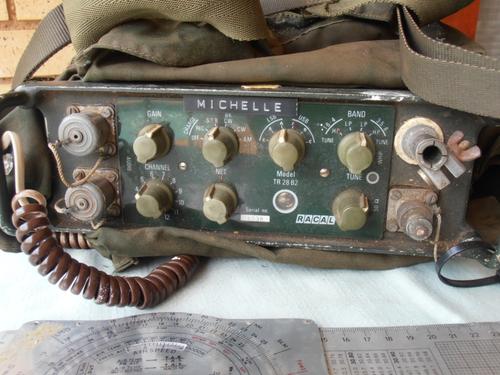
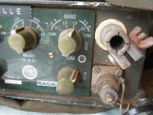
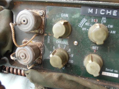
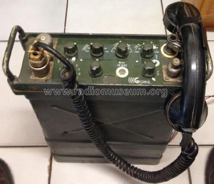
During these years, the Racal factory in England and its associated companies, of which “ Racal SMD ” (1) stands out in the Republic of South Africa, are closely linked to the supply of communication devices, their various accessories, as well as equipment test for the Portuguese Armed Forces. Of these supplies stand out the devices that we bring you today - the TR-28.
Still on the relationship between the “Racal” headquarters and its South African subsidiary, in due course the English government will pressure the first to leave this subsidiary, due to the racial problem then in force in that African country. Many engineers will then return to England, in no way affecting the production and creation of new models, as the South African human material was of the highest quality. Already with a new name and proving what was said, it emerges as a great manufacturer of electronic equipment for various purposes, including the military (for aeronautics).
With the TR-28, we stopped walking with the valves on our backs, however small they were. With its originality and technology we have definitely entered a new era. Portugal began to receive these receivers / transmitters for the three branches of the armed forces in the late sixties. They will remain in service for approximately twenty five years.
The TR-28 ( T ransmitter- R eceiver 28)they are an evolution of the troubled RT-14B (from SMD) being this one of the first military devices to use lateral bands. This type of modulation was already a success at that time (1965/66) with civilians, but it was seen as a curiosity for the society of the country, with “Racal SMD” being one of the responsible for its development and tactical application thanks to a set of engineers notable. We can say that the TR-28 is in fact designed one night, in March 1966 (2), on the table in the dining room of Ken Clayton - one of those responsible for its electronic development - based on the elements of the referred RT- 14. From that night until the prototype appears, a week will pass! That year tests are carried out (at the factory) in Angola in the Zambese valley and around the city of Salazar.The first models will be delivered to Rhodesian troops in 1967 (3).
Since the TR-28 is an exceptional radio, it is nevertheless an internationally unknown device. The explanation for this reality lies, in our opinion, in several facts of which we can highlight the aforementioned mistrust with which the side bands applied to military devices were felt , and the low penetration in the international market of devices originating from South Africa, whether they were from Racal or not! The intensive use of this device in Portugal (practically its only major user) does not help it to create a prominent place in the history of military communications, because… Portuguese decolonization was the last one, and the novelty of independence had already lost its impact. , relegating the designated barons and radios to oblivion .
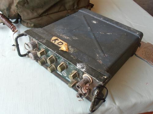
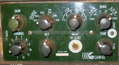
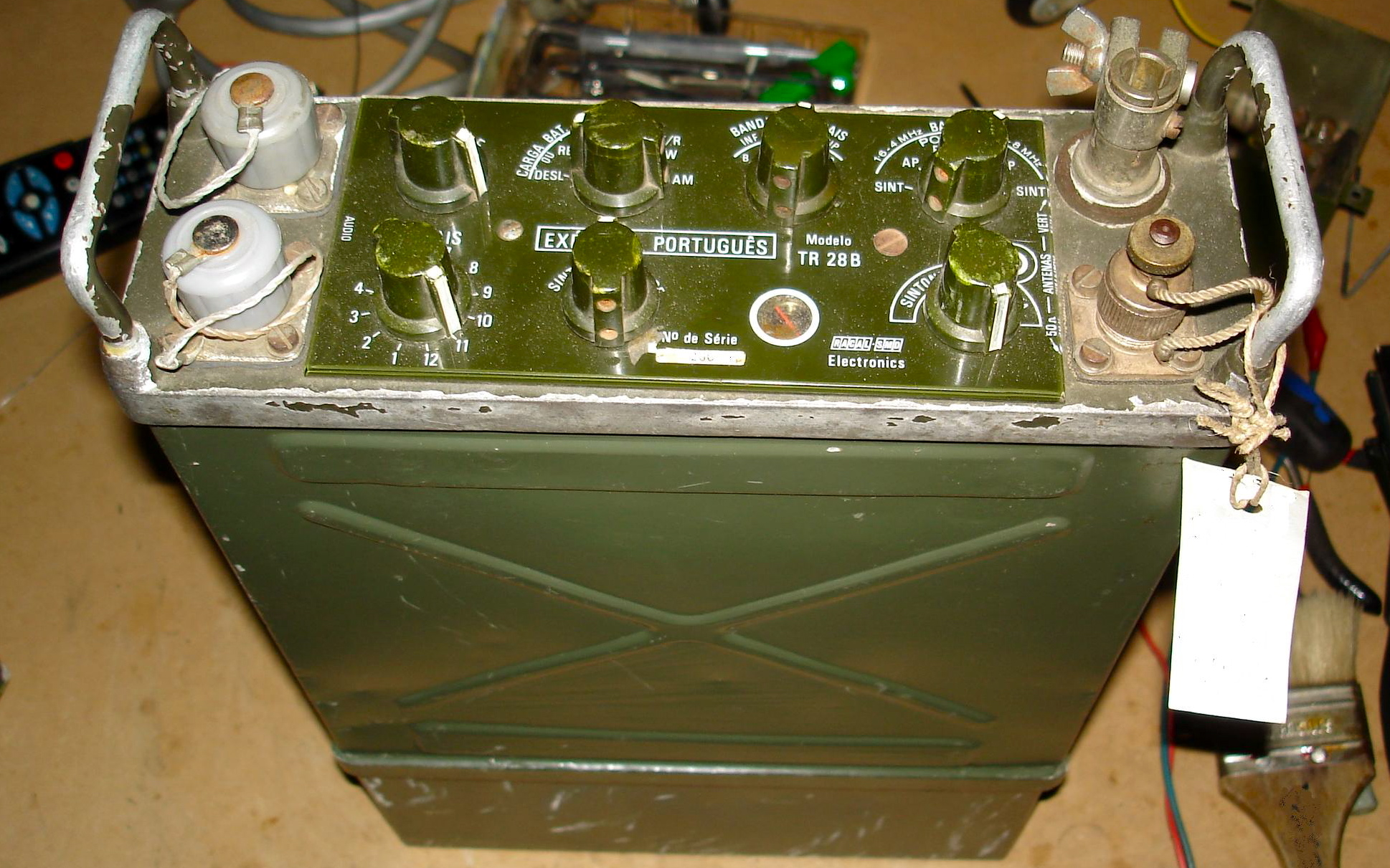
This series of radios to be used on the back, vehicular and fixed, operates in AM and side bands (upper / lower), in voice or spelling, from 2 to 8 Mc / s with a power of 25 / 30W. The TR-28 “family” comprises five main models (see the table below), all of them with frequencies fixed to crystals. The differences, as we will see, are not due to the number of channels and changes at the electronic level, but also to the exterior shape and colors with which they were originally painted.
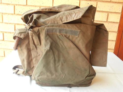
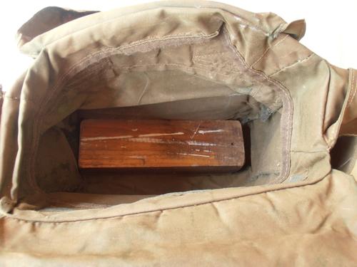
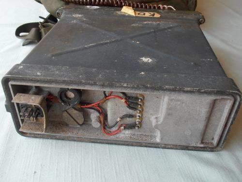
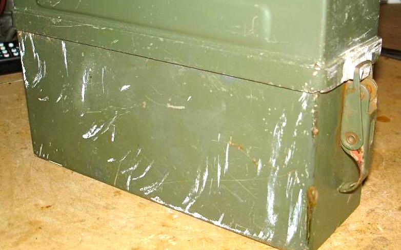
Worthy of note and going unnoticed at first glance, is the curious and valid technique used in the manufacture of the outer cases of all of them, including the battery case of the second model. If we repair well (and not counting the locks and the control panel) we notice that there are basically three pieces (two pieces for the first model's boxes, and three + one screwed to your 2nd model's battery box) in glued light alloy. and pressed together! The same technique is used to fix the two handles on all of them. Despite appearing to be a solution of poor durability in terms of military use, time has largely confirmed the opposite.
Many TR-28s will be assembled in Portugal on Standard Electrica / Centrel (under the control of the Transmission Weapons Directorate) with the inclusion of components from South Africa via Lourenço Marques, with Portugal participating in the development of the 36 channel versions. Virtually all TR-28s had the “ARMY PORTUGUESE” printed on the front panel. We point this out as it is a rare case. We cannot confuse this indication with the usual lettering found on small stickers or aluminum plates, identifying other devices (eg AVP-1). This indication appeared on all devices, regardless of the weapon in which they were distributed. To date, we have not seen, nor had we known in any way, of any other radio with such mention.
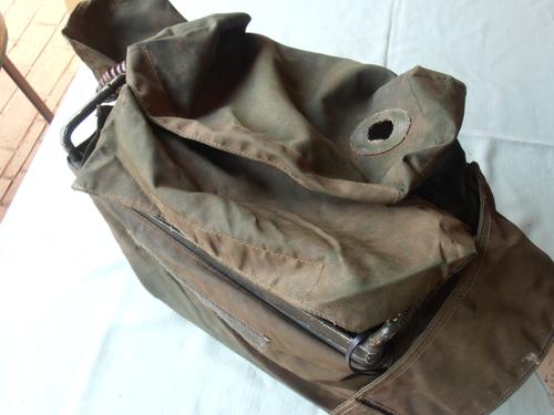
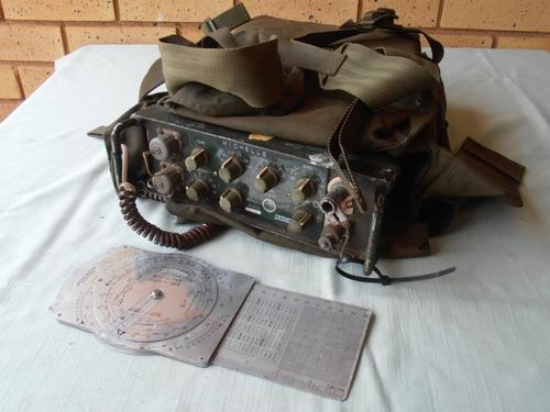
With regard to peripherals, two unique antenna systems stand out. The first comprised a roll of metallic wire, supported by a thin synthetic cable, wrapped in a small spool of aluminum. With the help of a weight, the antenna wire was thrown over a tree, the other end (that of the spool) being inserted into the socket for the antenna. Truly original was an antenna based on a real metallic measurement tape (in inches and the “Starett” brand), riveted to a special support. Fitted in the alveolus of the radio antenna, its precise extension, and later support at a high point, cut itimmediately to the desired frequency. Its winding was done with the help of a small outer crank, as in any good mason's tape! Although practice was not successful and was rarely used, it is nowadays almost forgotten.
These devices were equipped with two models of "capacitive plates" - one forming an integral part of the "back" of the transport backpack and the other detached and can be stored in a pocket or left on the ground. Without this plate well connected to the radio ground (serving as the ground plane ), the expected ranges were clearly impaired. Still on their relative power and just as a mere curiosity, and since the distance of forty years makes them eternally unpunished of a reprimand, we were told by old radio operators that it was possible to light a cigarrito on the antenna, when in issue.
On the colors with which they were originally painted, in the initial models (South African), a bright dark green (bronze green) characteristic of the British armed forces is highlighted. In national production and later repainting, various "military greens" were used, ranging from a dark and shiny "olive drab" to colors close to "RAL-6018", with quality textures being used in most national models. As a curiosity we have come across repainted specimens (?) In light gray “Navy” and blue “Air Force”.
With a completely different exterior, but with internal components similar to the military version "TR-28", Racal made a civilian version with the designation "TR-38D". We arrived at it, from its technical manual and texts in leaflets from its former representative in Mozambique (6), and by indication of a Portuguese technician who worked at the said factory. This version had frequencies of the spectrum assigned to civilians, having been used by farmers in the interior of the former overseas provinces.
In line with the natural development of the TR-28, a synthesized version (7), an idea that germinated in Portugal by engineers from Standart Electrica / Centrel, but which would have been abandoned because of April 1974 and the consequent end of hostilities would have been completed. in Africa.
Moving to the end of this article, we will not fail to mention information that was given to us a few years ago, not least because one of our readers may be the key to solving the mystery: that the Air Force (Corps of Paratroopers) ) would have had a specific version of the TR-28B2 (see table below), with a smaller battery box, to make the radio lighter! Until you see, this interesting indication - despite the unavoidable vehemence with which it was given to us - never obtained confirmation from safe sources belonging to Airborne Troops and with responsibility in their old transmission systems, nor in military or civilians connected to the Portuguese assembly line .
The radios we use today are not spontaneous generation. They had a whole evolution and that evolution, benchmarks, like the device we dealt with today. It is enough to notice, despite the distance in time, in the origin and in the technique, in the physical similarities existing between the TR-28 and the “our” recent P / PRC-425 that comes, in part, to replace it, to verify that whoever conceived aesthetically the latter should have had an old TR-28 as a reference on the drawing board!
List of Racal TR-28 models
(This listing is our responsibility, since we are unaware that it ever was done, only reliable information was found to partially advocate it. The conclusion we reached, and which we present to you in the first hand , results from the observation of many dozens of devices and their accessories, of vast technical and promotional literature of national and foreign origin read in the lines and between the lines, and of indications kindly provided by former military personnel of diverse hierarchy connected to their assembly, repair and tactical use in the continent and in the old overseas, as well as civilians directly related to national production.)
1st Model / 1st version :RACAL TR-28A, 12 frequencies (with 12 CR18U crystals), 25W output, command indications in English or Portuguese, with or without the indication “Portuguese Army” on the panel.
1st model / 2nd version: RACAL TR-28A2, 12 frequencies (w / 12 CR69U crystals), 25W output, command indications in Portuguese, with or without the indication “Portuguese Army” on the panel.
1st Model / 3rd version :RACAL TR-28B, 24 frequencies (w / 24 CR69U crystals), 25W output, command indications in Portuguese and “Portuguese Army” on the panel. This legend also appears on the 2nd model.
2nd Model / 1st version :RACAL TR-28B2, 24 frequencies (w / 24 CR69U crystals), 30W output, new exterior presentation and electronic modifications
3rd Model: RACAL TR-28C (?), Possible synthesized version, which will never have passed the conceptual phase.
Grades:
(1) The Durban-based South African firm “ Radio Electro-Equipement Co. “, gives way in 1937 to the firm “ SMD Manufacture Co. ” ( SMD are the initials of the names of its three founders: S teel, M adison and Dainty). In 1963, this house merges with the British company “Racal Electronics”, changing its name to “RACAL SMD”. This merger is followed by the change of headquarters from Durban to Pretoria. In 1969 he changed his name again, changing his name to “Racal Electronics South Africa Ltd.” or just “RESA”. Currently, these firms no longer exist, with English “Racal Electronics” included in the “Thales Group”, and “Racal Electronics South Africa Ltd.” in the “Grintek” group. When in 1963 “SMD” and “Racal” merged, a small part of “SMD” constitutes a new company, linked to the industrial group Barlows, dedicated to the development and manufacture of equipment for aeronautical communications and civil radios high quality (Barlows Wedley)
(2) “ The SSB manpack and his pioneers in South Africa ” 2nd part, in Radio Bygones nº 94
(3) For troops called “Rhodesian African Rifles” in “Bush telegraph” by Gordon Munro and Henton Jaaback, 2002
(4) The second and last battery pack, despite being made of three glued pieces (see text), was incomparably much more robust than the first model (made of a single piece). Due to its position, the battery pack is the first to suffer impacts on the ground, of the whole set.
(5) Perhaps the main source of problems in this device, in addition to an easy-to-replace relay and the fusion of wiring in very hot climates, resource wiring is being made in the middle of the operations area (Note mentioned by some radio assemblers)
(6) Representatives of “Racal Electronics South Africa Ltd.” in 1970:
Mainland
Portugal: Ondex Representações Electrónicas Ldª. (Lisbon)
Angola:
Racal Electronica Ldª. (Luanda)
Mozambique: Construtora
Rádio Eléctrica Ldª. (Lourenço Marques)
(7) We do not know if it would be the “TR-28C” version, mentioned in bulletins from the Military Academy.
João Freitas
(Text taken and adapted from an article of ours that appeared in the magazine “QSP”)
by Colonel José Manuel Canavilhas • Published in RTm CV , History , Tm Material • Tagged Angola , Campaign , African Wars , Mozambique , RACAL , TR-28
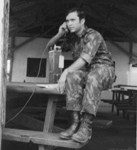
The Racal TR 28 in action in Mocambique
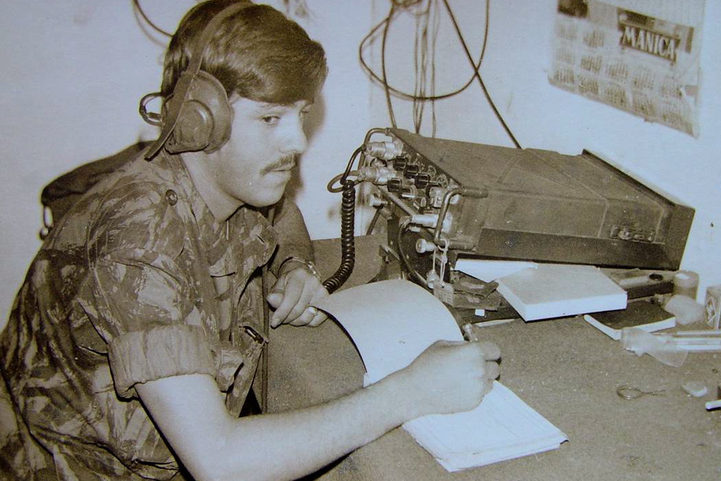
The Tr 28 B2 being used in Guinea